

The structure, selection and installation of power transformers
- Categories:Industry News
- Author:
- Origin:
- Time of issue:2019-08-11
- Views:0
(Summary description)
The structure of a power transformer
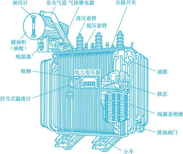
The power transformer is mainly composed of a magnetic core and a conductive coil. Both the coil and the iron core are installed in an oil tank filled with transformer oil, and the end of the coil is led to the outside of the oil tank through an insulating sleeve to connect to an external circuit. In addition to coils and iron cores, the transformer also has accessories such as oil tanks, oil pillows, tap changers, safety air ducts, gas relays and insulating sleeves. Figure 11-1 shows the outline structure of an oil-immersed power transformer.
图11-1 油浸式电力变压器的外形结构图
1. an iron core
The iron core is the magnetic circuit part of the transformer and the skeleton of the transformer structure. The primary and secondary windings of the transformer are wound on the iron core. The iron core is mostly made of silicon steel sheets with a thickness of 0.35~0.5mm, which are cross-laminated and coated with insulating paint.
2. Coil
The coil is the circuit part of the transformer, usually made of insulated copper wire or aluminum wire, and the outside of the copper wire is insulated with cable paper. The coil of the power transformer is wound in a cylindrical way, that is, the high and low voltage coils are sleeved together, all in a concentric circle, the low voltage coil is sleeved near the iron core, and the high voltage coil is sleeved outside the low voltage coil. The high and low voltage coils are separated by insulating cardboard, and oil passages are reserved, so that transformer oil can circulate freely between the two coils. Figure 11-2 shows the outline drawing of the high and low voltage coils.
图11-2 高、低压线圈的外形图
3. Fuel tank
The oil tank is the outer shell of the transformer, which is welded by steel plates. In addition to the iron core, coil and other components, there is transformer oil inside. The iron core and coil are immersed in transformer oil. The oil tank protects the iron core and coil from external forces and moisture. At the same time, the heat generated by the iron core and coil during operation is transferred to the tank wall through the convection of the transformer oil. A heat dissipation pipe is installed on the outside of the tank wall, and the hot oil in the tank passes through the tank wall and the heat dissipation pipe to dissipate heat to the surrounding air to cool the oil.
4. Transformer oil
Transformer oil is an excellent insulating oil. It can not only cool the coil and the iron core, but also enhance the insulation performance between the coils of each layer and between the coil and the iron core. Transformer oil circulates in the gap between the coils, conducts internal heat to the tank shell, and radiates into the air through the surface of the shell.
Transformer oil has the characteristics of high insulation strength, low viscosity, stable chemical properties, high ignition point, no impurities, and good arc extinguishing performance. According to its freezing point, it is divided into No. 10 (freezing point is 10 ℃), No. 25 (freezing point is 25℃) and No. 45 (freezing point is 45℃) 3 kinds of specifications. When replenishing and replacing transformer oil, you must pay attention to the same oil number.
5. Oil pillow
The oil pillow, also known as the oil conservator, is a cylindrical container installed on the top of the oil tank and connected to the oil tank of the transformer through a pipeline. The transformer oil fills the oil tank and reaches half of the oil pillow. When the transformer is running, the temperature rises and the oil expands, and the oil in the oil tank flows into the oil pillow; when the oil temperature drops, the oil flows into the oil tank again, so that the oil tank is always full of oil. An oil gauge is installed on the oil pillow, and the oil level can be monitored through the oil gauge.
6. Insulating sleeve
The insulating sleeve is composed of an outer porcelain sleeve and a conductive rod in the center. When the outlet wire of the transformer is led from the inside of the oil tank to the outside of the oil tank, it must pass through the insulating sleeve to insulate the live wire from the grounded oil tank. Insulating bushings are generally made into a multi-level umbrella shape to increase the surface discharge distance. The high-voltage bushing has a tall shape and the low-voltage bushing has a short shape.
7. Safe airway
The safety air duct is also called an explosion-proof tube, which is installed on the upper part of the fuel tank top cover. It is a long steel tube with an explosion-proof membrane on the upper end. The role of the explosion-proof tube is to protect the transformer. When a fault occurs inside the transformer, the temperature rises and the oil decomposes violently, producing a lot of explosive gas. When the pressure inside the fuel tank exceeds a certain value, the oil and gas will break through the explosion-proof film of the explosion-proof tu
The structure, selection and installation of power transformers
(Summary description)
The structure of a power transformer
The power transformer is mainly composed of a magnetic core and a conductive coil. Both the coil and the iron core are installed in an oil tank filled with transformer oil, and the end of the coil is led to the outside of the oil tank through an insulating sleeve to connect to an external circuit. In addition to coils and iron cores, the transformer also has accessories such as oil tanks, oil pillows, tap changers, safety air ducts, gas relays and insulating sleeves. Figure 11-1 shows the outline structure of an oil-immersed power transformer.
图11-1 油浸式电力变压器的外形结构图
1. an iron core
The iron core is the magnetic circuit part of the transformer and the skeleton of the transformer structure. The primary and secondary windings of the transformer are wound on the iron core. The iron core is mostly made of silicon steel sheets with a thickness of 0.35~0.5mm, which are cross-laminated and coated with insulating paint.
2. Coil
The coil is the circuit part of the transformer, usually made of insulated copper wire or aluminum wire, and the outside of the copper wire is insulated with cable paper. The coil of the power transformer is wound in a cylindrical way, that is, the high and low voltage coils are sleeved together, all in a concentric circle, the low voltage coil is sleeved near the iron core, and the high voltage coil is sleeved outside the low voltage coil. The high and low voltage coils are separated by insulating cardboard, and oil passages are reserved, so that transformer oil can circulate freely between the two coils. Figure 11-2 shows the outline drawing of the high and low voltage coils.
图11-2 高、低压线圈的外形图
3. Fuel tank
The oil tank is the outer shell of the transformer, which is welded by steel plates. In addition to the iron core, coil and other components, there is transformer oil inside. The iron core and coil are immersed in transformer oil. The oil tank protects the iron core and coil from external forces and moisture. At the same time, the heat generated by the iron core and coil during operation is transferred to the tank wall through the convection of the transformer oil. A heat dissipation pipe is installed on the outside of the tank wall, and the hot oil in the tank passes through the tank wall and the heat dissipation pipe to dissipate heat to the surrounding air to cool the oil.
4. Transformer oil
Transformer oil is an excellent insulating oil. It can not only cool the coil and the iron core, but also enhance the insulation performance between the coils of each layer and between the coil and the iron core. Transformer oil circulates in the gap between the coils, conducts internal heat to the tank shell, and radiates into the air through the surface of the shell.
Transformer oil has the characteristics of high insulation strength, low viscosity, stable chemical properties, high ignition point, no impurities, and good arc extinguishing performance. According to its freezing point, it is divided into No. 10 (freezing point is 10 ℃), No. 25 (freezing point is 25℃) and No. 45 (freezing point is 45℃) 3 kinds of specifications. When replenishing and replacing transformer oil, you must pay attention to the same oil number.
5. Oil pillow
The oil pillow, also known as the oil conservator, is a cylindrical container installed on the top of the oil tank and connected to the oil tank of the transformer through a pipeline. The transformer oil fills the oil tank and reaches half of the oil pillow. When the transformer is running, the temperature rises and the oil expands, and the oil in the oil tank flows into the oil pillow; when the oil temperature drops, the oil flows into the oil tank again, so that the oil tank is always full of oil. An oil gauge is installed on the oil pillow, and the oil level can be monitored through the oil gauge.
6. Insulating sleeve
The insulating sleeve is composed of an outer porcelain sleeve and a conductive rod in the center. When the outlet wire of the transformer is led from the inside of the oil tank to the outside of the oil tank, it must pass through the insulating sleeve to insulate the live wire from the grounded oil tank. Insulating bushings are generally made into a multi-level umbrella shape to increase the surface discharge distance. The high-voltage bushing has a tall shape and the low-voltage bushing has a short shape.
7. Safe airway
The safety air duct is also called an explosion-proof tube, which is installed on the upper part of the fuel tank top cover. It is a long steel tube with an explosion-proof membrane on the upper end. The role of the explosion-proof tube is to protect the transformer. When a fault occurs inside the transformer, the temperature rises and the oil decomposes violently, producing a lot of explosive gas. When the pressure inside the fuel tank exceeds a certain value, the oil and gas will break through the explosion-proof film of the explosion-proof tu
- Categories:Industry News
- Author:
- Origin:
- Time of issue:2019-08-11
- Views:0
The structure of a power transformer
The power transformer is mainly composed of a magnetic core and a conductive coil. Both the coil and the iron core are installed in an oil tank filled with transformer oil, and the end of the coil is led to the outside of the oil tank through an insulating sleeve to connect to an external circuit. In addition to coils and iron cores, the transformer also has accessories such as oil tanks, oil pillows, tap changers, safety air ducts, gas relays and insulating sleeves. Figure 11-1 shows the outline structure of an oil-immersed power transformer.
1. an iron core
The iron core is the magnetic circuit part of the transformer and the skeleton of the transformer structure. The primary and secondary windings of the transformer are wound on the iron core. The iron core is mostly made of silicon steel sheets with a thickness of 0.35~0.5mm, which are cross-laminated and coated with insulating paint.
2. Coil
The coil is the circuit part of the transformer, usually made of insulated copper wire or aluminum wire, and the outside of the copper wire is insulated with cable paper. The coil of the power transformer is wound in a cylindrical way, that is, the high and low voltage coils are sleeved together, all in a concentric circle, the low voltage coil is sleeved near the iron core, and the high voltage coil is sleeved outside the low voltage coil. The high and low voltage coils are separated by insulating cardboard, and oil passages are reserved, so that transformer oil can circulate freely between the two coils. Figure 11-2 shows the outline drawing of the high and low voltage coils.
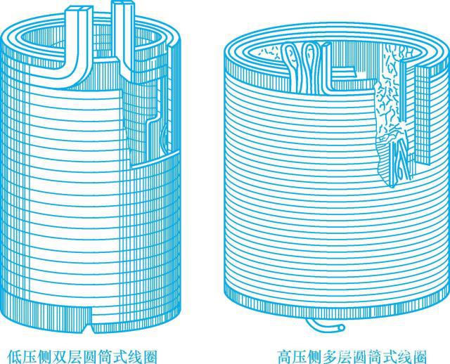 图11-2 高、低压线圈的外形图
3. Fuel tank
The oil tank is the outer shell of the transformer, which is welded by steel plates. In addition to the iron core, coil and other components, there is transformer oil inside. The iron core and coil are immersed in transformer oil. The oil tank protects the iron core and coil from external forces and moisture. At the same time, the heat generated by the iron core and coil during operation is transferred to the tank wall through the convection of the transformer oil. A heat dissipation pipe is installed on the outside of the tank wall, and the hot oil in the tank passes through the tank wall and the heat dissipation pipe to dissipate heat to the surrounding air to cool the oil.
4. Transformer oil
Transformer oil is an excellent insulating oil. It can not only cool the coil and the iron core, but also enhance the insulation performance between the coils of each layer and between the coil and the iron core. Transformer oil circulates in the gap between the coils, conducts internal heat to the tank shell, and radiates into the air through the surface of the shell.
Transformer oil has the characteristics of high insulation strength, low viscosity, stable chemical properties, high ignition point, no impurities, and good arc extinguishing performance. According to its freezing point, it is divided into No. 10 (freezing point is 10 ℃), No. 25 (freezing point is 25℃) and No. 45 (freezing point is 45℃) 3 kinds of specifications. When replenishing and replacing transformer oil, you must pay attention to the same oil number.
5. Oil pillow
The oil pillow, also known as the oil conservator, is a cylindrical container installed on the top of the oil tank and connected to the oil tank of the transformer through a pipeline. The transformer oil fills the oil tank and reaches half of the oil pillow. When the transformer is running, the temperature rises and the oil expands, and the oil in the oil tank flows into the oil pillow; when the oil temperature drops, the oil flows into the oil tank again, so that the oil tank is always full of oil. An oil gauge is installed on the oil pillow, and the oil level can be monitored through the oil gauge.
6. Insulating sleeve
The insulating sleeve is composed of an outer porcelain sleeve and a conductive rod in the center. When the outlet wire of the transformer is led from the inside of the oil tank to the outside of the oil tank, it must pass through the insulating sleeve to insulate the live wire from the grounded oil tank. Insulating bushings are generally made into a multi-level umbrella shape to increase the surface discharge distance. The high-voltage bushing has a tall shape and the low-voltage bushing has a short shape.
7. Safe airway
The safety air duct is also called an explosion-proof tube, which is installed on the upper part of the fuel tank top cover. It is a long steel tube with an explosion-proof membrane on the upper end. The role of the explosion-proof tube is to protect the transformer. When a fault occurs inside the transformer, the temperature rises and the oil decomposes violently, producing a lot of explosive gas. When the pressure inside the fuel tank exceeds a certain value, the oil and gas will break through the explosion-proof film of the explosion-proof tube and spray out, so that the explosion or deformation of the fuel tank can be avoided. Small transformers generally do not have explosion-proof tubes. Generally speaking, only transformers above 100kVA are equipped with oil pillows, and transformers above 1000kVA are equipped with explosion-proof tubes.
8. Gas relay
Gas relays are commonly known as Buchholz relays. It is installed in the pipeline between the oil tank and the oil pillow. The gas relay is an important protection device that reflects the internal fault of the transformer tank. When there are faults such as short circuit between winding turns and partial discharge in the transformer oil tank, the surrounding transformer oil will be decomposed to produce gas. The gas will enter the oil pillow through the gas relay from the oil tank and run into the air. At the same time, the air flow drives the action of the gas relay. mechanism. When the internal fault of the transformer reaches a certain level, the gas relay will act and send out an alarm signal. When the internal fault of the transformer is serious enough to damage the equipment and affect the safe operation, the gas relay action mechanism automatically cuts off the power to stop the operation of the transformer, ensuring the safety of the transformer.
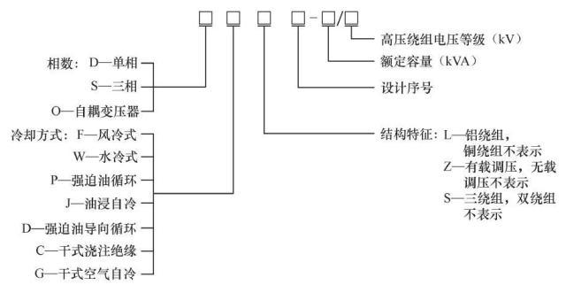
Transformer model
The meaning of the transformer model is as follows:
The main parameters of the transformer
1. Rated capacity
The rated capacity of a transformer refers to the maximum apparent power that the transformer can output when it is working under rated voltage, rated current, rated frequency and rated use conditions, in units of volt-ampere (VA) and kilovolt-ampere (kVA).
2. Rated voltage
The rated voltage refers to the no-load voltage value of the secondary side (also known as the secondary) when the rated voltage is applied to the primary side (also known as the primary) of the transformer, and the unit is expressed in volts (V) or kilovolts (kV).
3. Rated current
Transformer primary and secondary rated current (I1N, I2N) refers to the line current allowed to pass through the primary and secondary windings for a long time under the rated voltage and rated ambient temperature so that each part of the transformer does not exceed the allowable temperature. The unit is ampere (A).
4. Turn ratio
The transformation ratio refers to the ratio of the rated voltage of one winding to the rated voltage of another winding with a lower or equal rated voltage. The transformation ratio is not less than 1.
5. Impedance voltage
Impedance voltage is also called short-circuit voltage, which represents the percentage of voltage loss generated on the transformer's own impedance when the transformer passes the rated current, and is measured in the transformer short-circuit test. The value of impedance voltage is generally 4.5% to 6%. The value of impedance voltage represents the size of the internal impedance of the transformer, which is an important parameter of the transformer.
6. No-load current
When the secondary side of the transformer is open and the rated voltage is applied to the primary side, the current flowing in the primary winding is called the no-load current.
7. No-load loss
No-load loss refers to the loss when the rated AC voltage is applied to one winding of the transformer and the other windings are open. The unit is expressed in watts (W) or kilowatts (kW). No-load loss characterizes the economic performance of the transformer.
8. Short circuit loss
When the secondary side is short-circuited and the primary winding passes the rated current, the power consumed is the short-circuit loss of the transformer. The short-circuit loss also characterizes the economic performance of the transformer.
9. Connection group
The connection group refers to the phase relationship of the line voltage or line current on the primary and secondary side when the primary and secondary windings of the transformer are connected in a certain way. The connection group of the three-phase transformer is related to the winding direction, the markings of the head and the end, and the connection method of the three-phase winding.
Selection of transformer
The capacity of the transformer can be selected as follows:
In the formula, the simultaneity ratio is the ratio of the actual capacity of the equipment put into operation at the same time to the total capacity of the electrical equipment, which is generally about 0.7; the power factor of the electrical equipment is generally 0.8 to 0.9; the efficiency of the electrical equipment is generally 85% to 90%.
When the load is a motor, selecting the capacity of the transformer should also consider that the starting current of the motor is 4 to 7 times the rated current, and the transformer should be able to withstand this impact. Therefore, in the directly started motor group, the power of the largest motor should not exceed 30% of the transformer capacity; at the same time, it should be ensured that the motor with the largest capacity is within the power supply range of the same distribution transformer. The terminal voltage of the electrical equipment cannot be lower than 75% of the rated voltage of the transformer.
Example: A certain factory has 4 55kW electric motors, and 4 motors are running at the same time during the busy season. Try to select the transformer capacity.
Solution: The transformer capacity is (power factor is 0.85, efficiency is 90%)
When using decompression start, two distribution transformers of 100kVA and 180kVA can be selected for parallel operation; when using direct start, one 315kVA transformer should be selected.
Transformer installation
1. Installation of single pole change table
This type of transformer is often used on both sides of urban streets (the transformer installation platform, hereinafter referred to as the transformer). This kind of transformer has simple structure, convenient assembly and material saving. It is suitable for transformers with a capacity of 50kVA and below. It installs transformers, high voltage drop-out fuses, high and low voltage arresters and low voltage fuses on a pole. , See Figure 11-3.
When installing a single pole transformer, usually a bearing (mounting base supporting the transformer, usually made of angle steel) is erected on the load-bearing pole, and the pole-mounted transformer is installed on the bearing. The height of the bearing seat from the ground is generally 2.5~3.0m. Install a fuse frame beam (also called a busbar arm) at a distance of 1.8~2.0m from the bearing seat, and install a fuse arm at one end of the busbar arm and a lightning arrester at the other end. For safety, the low-voltage side of the transformer should face the pole and the high-voltage side outward. The pole is generally 10m long, with a buried depth of 1.8~2.0m. The transformer shell, the transformer neutral point and the grounding of the arrester share the same grounding down conductor, which is connected to the same grounding device, which is called the three-point common ground.
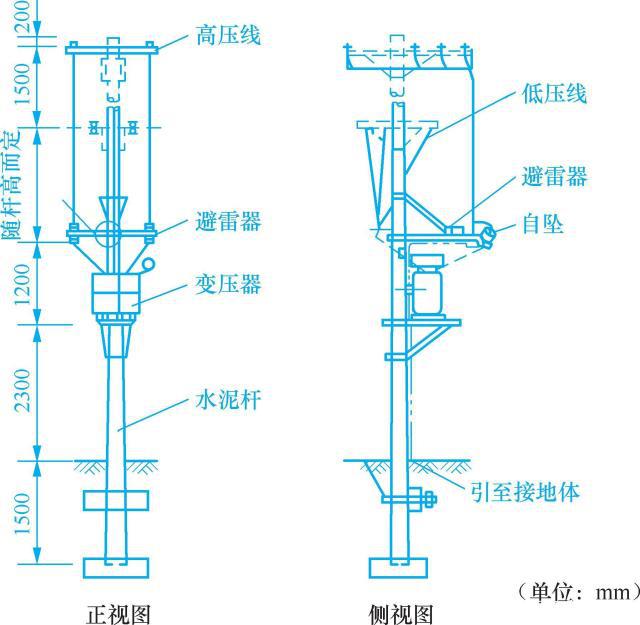 图11-3 单杆变台
2. Installation of the double-pole variable table
The double-pole transformer is stronger than the single-pole transformer, but it uses more materials and higher cost. It is suitable for transformers with a capacity of 50~315kVA. It is to make another contract at a distance of 2~3m from the high voltage pole (main pole). The 7.5m long electric pole (secondary pole) is built with two channel steels or angle steels at a height of 2.5-3.0m from the ground to form a shelf for the transformer to form an "H" deformation platform. This type of platform is mostly used on both sides of urban roads, as shown in Figure 11-4.
During installation, install a busbar at a distance of 1.8~2.0m from the upper part of the channel steel, and pull up a short busbar, install a high-voltage arrester at the end, connect the high-voltage leads of the transformer to the busbar, and install a low-voltage isolation switch at the other end of the busbar. Install the fuse frame beam and fuse holder at the main pole 4.5~5.0m from the ground. The high-voltage down-conductor can be led down directly or by changing the direction of the top arm, and connected to the upper wiring of the drop-out fuse via a pin-type porcelain bottle. On the pillar.
3. Masonry of ground type transformation platform
The ground bench is relatively firm, saves materials, has a lower cost, and is convenient for maintenance. It is generally built on the ground with bricks or stones and concrete. The terminal of the high-voltage line can double as the start-end rod of the low-voltage line, as shown in Figure 11-5.
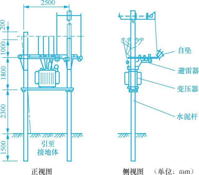 图11-4 双杆变台
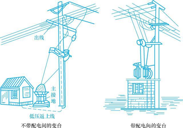 图11-5 地台式变台
The height and top area of the platform depend on the size of the transformer. Generally, the height of the platform is preferably 1.5-2.0m. When the height is less than 1.5m, a fixed barrier with a height of not less than 1.7m should be installed around it. Keep a distance of 1.5m between the barrier and the live part. Each side of the top of the platform should exceed the transformer shell by 0.3m, generally the length is 1.5~2.5m, and the width is 1.0~1.5m.
4. Masonry of floor-standing transformation platform
The floor-standing variable platform should have a solid foundation. The foundation is generally made of bricks and stones, and the surface is plastered with 1:2 cement mortar. The height of the foundation surface from the ground should not be less than 300mm, see Figure 11-6. The door of the transformation platform should be locked, and a warning sign stating "High Voltage Danger, Stop!" should be hung on the door.
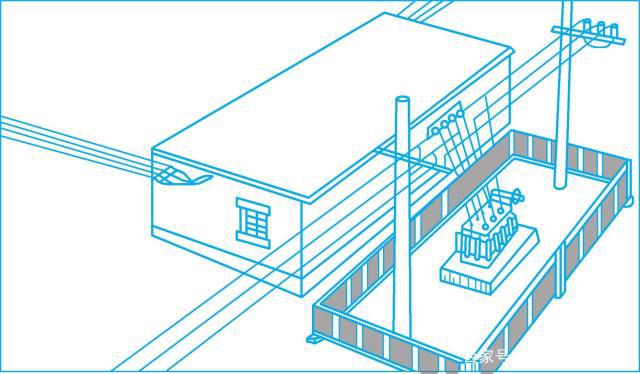 图11-6 落地式变台
In order to ensure safety and prevent people and animals from approaching the live parts, a fence or fence with a height of not less than 1.7m should be set around the transformer platform. The net distance from the transformer shell to the fence or fence should not be less than 1.0m, and the net distance from the door should not be less than 2.0 m. The door of the fence or fence should open outwards. The distance between the bars of the fence and the net distance between the horizontal fence below and the ground shall not be greater than 200mm.
Scan the QR code to read on your phone


Mobile station
More exciting waiting for you!
Copyright © 2021 Chenglai Electric Technology Co., Ltd. 吉ICP备16001082号